We’re building some sonic frames for the Long Beach A LOT project in September and will use them again for SoundWalk 2013. These need to be activated by visitors and we decided to use some illuminated pushbutton switches as enticements. This requires a very minor hack to the cheap little car amplifier inside each frame, documented here so the next seven or eight units can be readied for action.
You can save yourself a lot of aggravation—I speak from experience here—by reading this entire set of instructions before starting. Just sayin’…
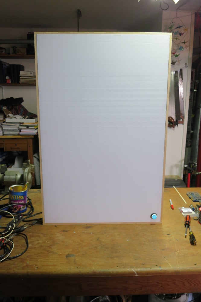
Goal
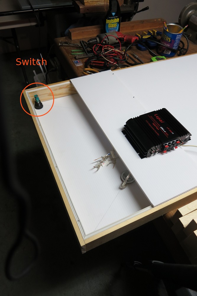
I chose a corner mounting position for the switch for a couple reasons: it allows the same mounting approach for portrait and landscape layout, plus the proximity to two edges should make the design less susceptible to public abuse. We could reinforce the panel if desired.
For reference, the switch was positioned 1-3/4″ from the outer edge of the wooden frame, or 1-3/8″ from each edge of the “plastic cardboard” resonator panel. That’s just enough to provide clearance for the micro-switch mechanism attached to the button.
The depth of the box proved just sufficient for clearance of the rear part of the switch once the slide-on terminal clips were attached. Since anything touching the panel will buzz when loud sounds are played—I found cords were usually the culprit—we need to make sure everything is either isolated from the panel or firmly anchored to it.
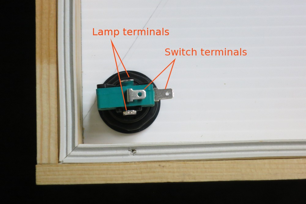
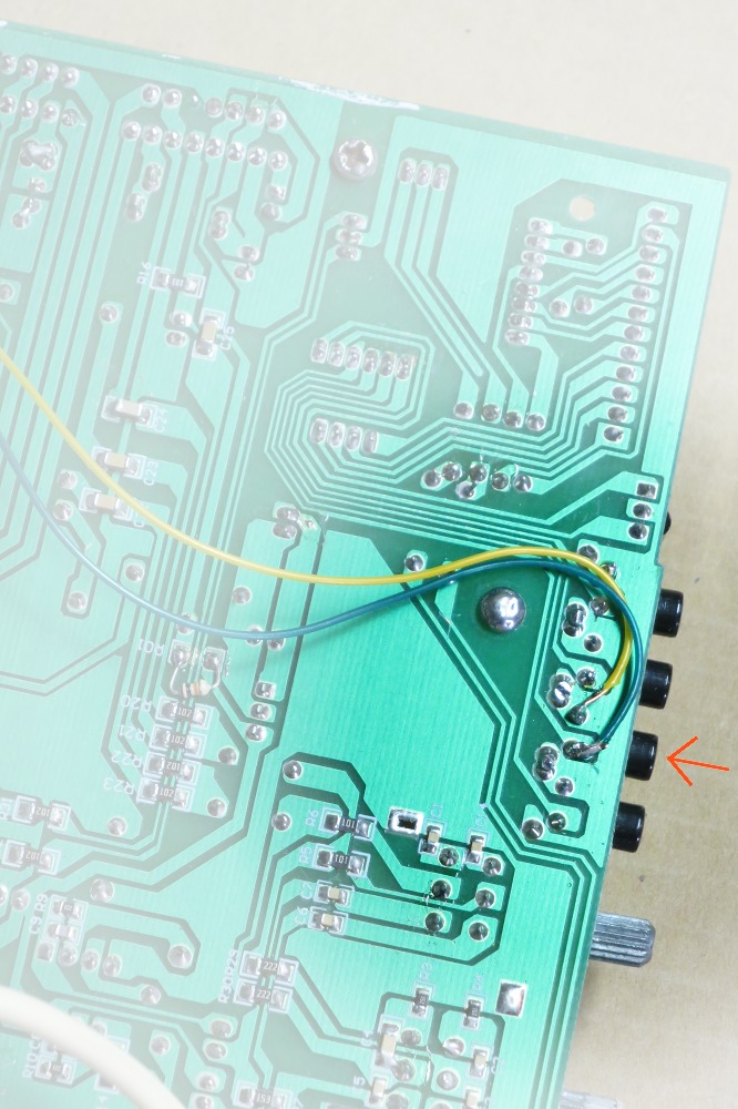
The LePai amp we’re using is an astonishing marriage of 2 x 2″ of modern microciruitry—for reading data from USB and micro-SD, plus a miniature radio receiver—with a single-layer(!) analog PCB hosting the power amps, knobs, display, and pushbuttons. This cruder part of the assembly is where we’ll do our work: taking 12V power for the 3W lamp inside the switch, and intercepting the Play/Pause function by wiring into that N/O button in parallel. Simple.
Tools
- #1 and #2 Phillips screwdrivers
- Wire-stripper
- Soldering iron
- Crimp terminal tool
- Sheet metal nibbler and/or metal file
Materials
- Lead resin-core solder (these are NOT RoHS units!)
- 2′ length of 4-conductor 26 AWG telephone extension wire
- 4 ea. crimp-style female spade terminals, or “sliders”
Part 0: Power off!
It’s easy to forget this step, but until the “smoke test” at the end, the amp is powered off, disconnected from its wall-wart transformer, and detached from all other wires.
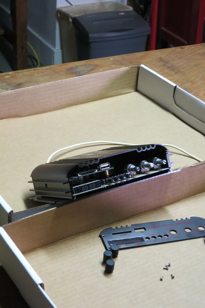
The front plate is easily removed by sliding the knobs off and then undoing the four little screws at the outer corners. It’s not really necessary to remove this plate, but it will allow inspection of the Play/Pause button wires we’re adding on final assembly, so I recommend just taking it off and setting it aside.
Congratulations on voiding the manufacturer’s warranty! Now you can marvel at the fine hand craftsmanship. One knob—marked BASS—was reinforced with masking tape, though I couldn’t tell whether it was due to stripping or just a preventive measure for when the proud new owner tries to crank their “45W RMS” bass section up to 11 (anyone paying sub-$40 for raw, cranking base power is courting disappointment…).
Part 1: Remove the PC board
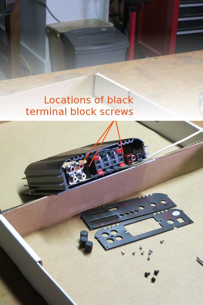
The rear panel comes off easily as well, but it has three additional screws to hold the rear terminal blocks and RCA jacks against it while wires and plugs are inserted. Remove these plus the four corner screws, and the panel pops right off.
Do not try to slide the power board out yet! The audio amplifier chips are still held firmly in place against the wall of the case!
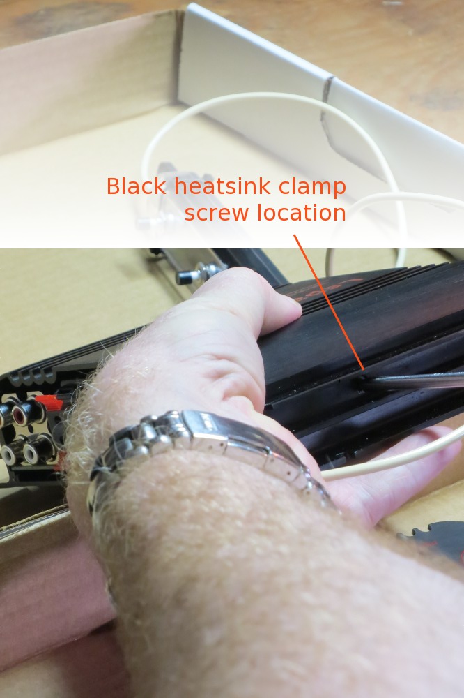
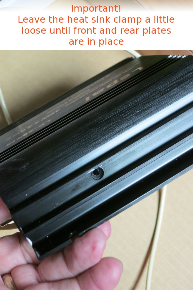
On the right side of the case—as viewed from the rear—you will find the one remaining screw. This is a black self-tapping screw—the one on my unit looked like a drywall screw to me, not a sheet-metal self-tapper—that holds a piece of bent metal in place and clamps the thermal tabs of the little power amp chips to the side wall of the case. This is the only design detail suggesting any real utility for the fancy extruded aluminum case’s shape.
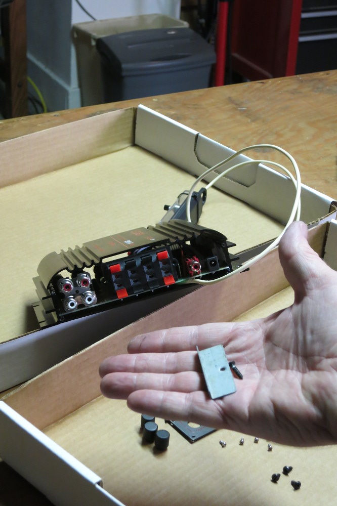
Once the screw is removed, tip the entire chassis face-end up and the heatsink clamp should just drop out. Set it aside with the screw.
You can now carefully slide the entire PCB assembly out of the case. The power PCB rests inside little channels inside the case. Try pushing against the buttons or knob shafts from the front until the board begins to emerge from the rear of the case; then grasp the lower board edges and draw it out of the case.
Look out for the white lithium grease on the audio amp chips!
The grease is probably all over the side of the case where the heatsink clamp and screw were removed. Do not wipe it off; you’ll need it during reassembly and probably don’t want to drive across town to see whether Radio Shack still carries it….
It’s OK to wipe it off your hands, which are also likely well-coated by now.
Part 2: Add four wires
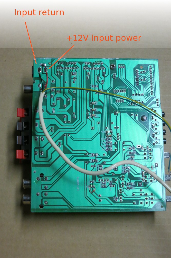
First, we need to get power to the lamp. Since these are the “mains” for the LePai unit, I suggest using the black and red wires as the power pair. The input jack is soldered to the power board at a couple of points that are easy to intercept.
If you use phone extension wire, as I did, bear two things in mind:
- This is solid wire. Be careful not to nick it when stripping it, as it breaks easily.
- The insulation melts easily! Phone wire is seldom soldered and uses low-temp plastic insulation.
If you like, shorten these two lamp power wires, leaving the green and yellow pair about 4″ longer. Unless you’re a big fan of slack loops, this will get rid of wire you don’t need and help keep the four-conductor cable in place during reassembly.
I recommend tinning the wires lightly first, then just “resoldering” to the existing back-side blobs on the PCB. The result is as shown the photo: good enough. (In fact, by now you are probably noticing a mix of SMT and through-hole components soldered to the trace-side of the board. Feel good about yourself and just embrace that cottage-industry feeling!)
This is also a great time to check for cold-solder problems and other artifacts of original manufacture. The four audio outputs are indeed independent—if very oddly routed—and I fixed two very questionable joints near the output terminal block. The unit seemed louder when I reassembled it than before I first took it apart to modify it, so I’d recommend this step. Do a visual….
Part 3: Notch the rear panel and reassemble the amp
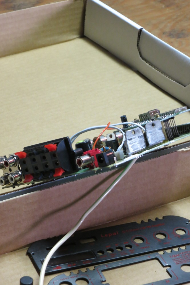
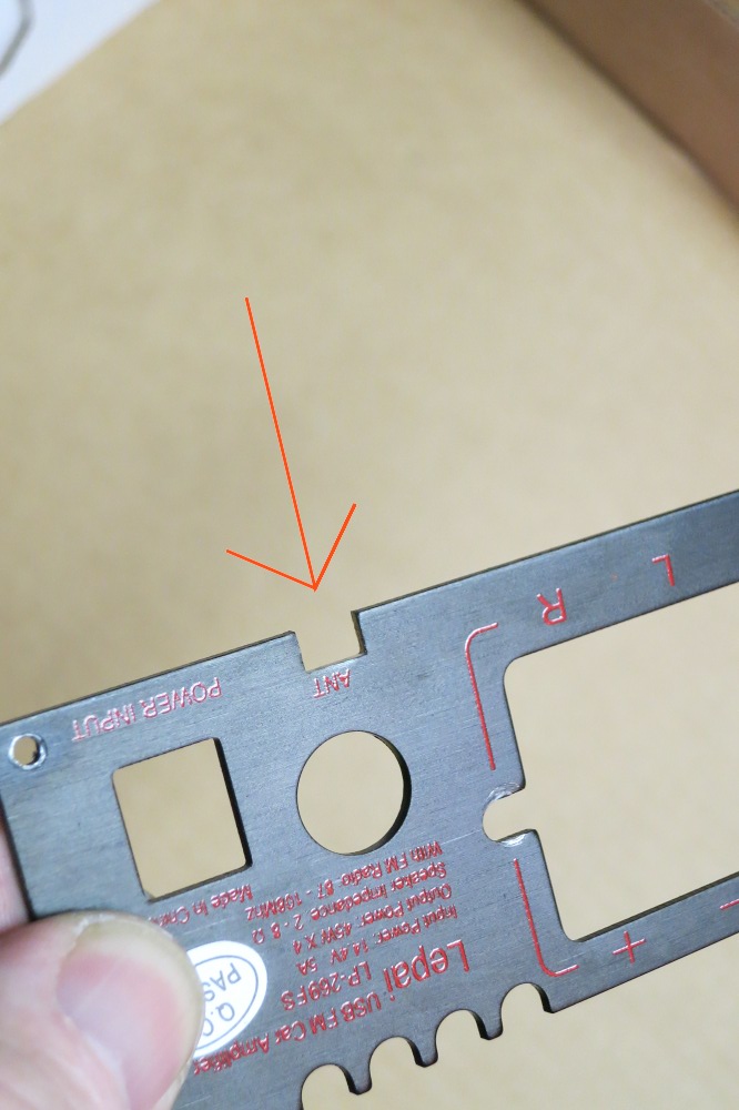
The new wire needs some way to exit the case to be connected to the switch. I cut a little notch just below the antenna jack on the real panel.
I used a little nibbler tool for this, but a drill and metal file would work as well. It’s not worth breaking jeweler’s saw blades on rough work…. (It was tempting to just remove the jack and reuse the hole—we don’t need the radio—but that would actually have taken more effort.)
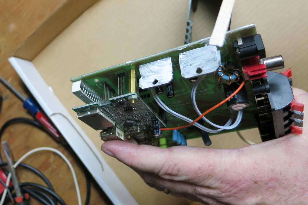
Reassembly is trickier than you might think, in part because of the lithium grease which should be liberally slathered on the faces of the amp chip thermal tabs. If it’s gotten somewhere else during this process, restore it to its proper place on the backs of the amp tabs before sliding the PCB assembly back into position.
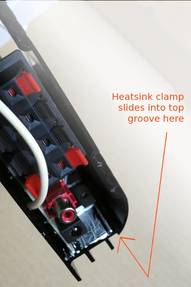
The next trick is replacing the heatsink clamp and securing it with the self-threading screw. The clamp is shaped like an upside-down “L” of metal, and the foot of the L slides into the upper-most channel of the extruded aluminum case. However, you do not want to smear lithium grease everywhere and the clamp needs to be placed with its rear edge about 1-1/2″ inside the rear of the case so the hole will align with the hole in the case; this takes a little finesse.
The photo gives you a good idea about where most of the grease ends up once the board has been slid into position. The important thing is that enough grease makes it between the tabs and the case to provide a conductive layer when the tabs and case are clamped together.
Once you’ve managed the magic of getting the clamp into position, you can hold it in place with one finger inside the case while tipping the case itself on its side so you can see to align the holes. Note that the screw does not thread through either of the audio amp thermal tab mounting holes, but instead passes between the bodies of the two amplifiers so it can draw on the clamp to hold both in place! (One less screw, one less assembly step: cost reduction in action!)
Finally, do not tighten the heatsink clamp screw completely just yet. You may need a little play so the board can move to a neutral position as the front and rear panel are attached.
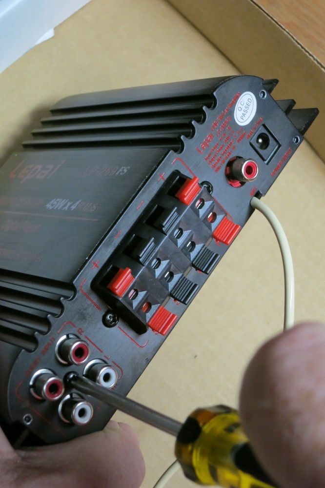
This part is easy. Replace the rear plate, guiding the new wire out through the new slot. Insert and tighten the four corner screws into place. Then set and tighten the three screws that secure the terminal blocks and RCA jacks into place.
Inspect the board from the front to make sure the new wires to the Play/Pause button haven’t gotten hung up anywhere and that there are no obvious shorts (assuming you melted the insulation a bit during soldering). You can insert some electrical tape or other insulator if you’re worried about electrical contact with the case. Now reattach the front plate, replacing the four corner screws, and reattach the TREBLE, BASS, and VOLUME buttons.
Part 4: Finish the job
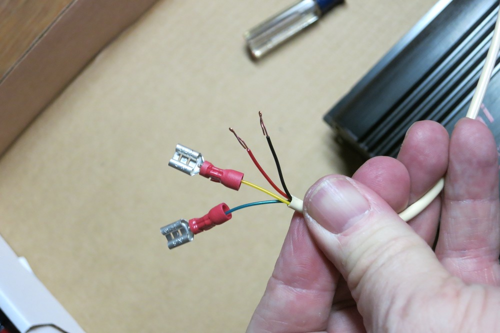
At this point, the amp is reassembled and it would be a good idea to give it a power up and “smoke test”. Before doing so, strip the wires at the other end of the cable we’ve just added and crimp on the four female spade terminals. This will make it easier to keep everything separated when you test the unit .
The wire is very thin, so I recommend doubling it back on itself before inserting in the terminal and crimping. Be prepared to waste a few terminals in case you over-crimp and shear the wire in the process.
Make sure the new cable wires are not touching each other before you power up the amp! (…or even AFTER you do. You’ll fry the transformer, since we haven’t added a fuse.) Use a multi-meter if you’re patient enough, and check for 12V between the red and black leads. Now turn on the amp power, listen for pops and sniff for smoke.
If all’s well, proceed with audio connection and test!
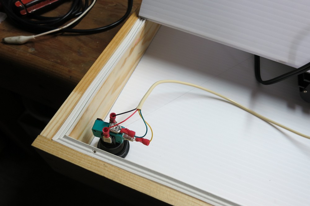
Switch connection will wait until the final assembly takes place, but will look something like the photo.
Improvements
Of course, this could be better.
How about a fuse?
First of all, I noticed absolutely no fusing in the LePai unit. (Of course, the LePai engineering team may have tried the old engineer’s trick of sticking a low-wattage resistor somewhere next to the power rails to act as a one-shot safety fuse, but I’m thinking not.) So we’re at the mercy of the wall wart failing gracefully in event of a short circuit or switch meltdown. My guess is it will do so, but a fuse in the unit would have been a great enhancement.
Remote control testing?
I found the remote—which has a bulb on the front, and therefore must be infrared?—still worked when pointed at the front of the box, which was sealed up with the amplifier inside. But the plastic cardboard is translucent, so there’s a good chance this won’t work once the photo-paper is adhered to the front of the unit, isn’t there? Also, who knows whether one remote affects all amps in one room—it’s designed for automotive use, so I imagine all units use the same encoding and frequency—or if each unit is somehow slaved to its original partner? Both questions are worthy of further investigation, but not of derailing the project.
How about a real power switch?
If the amp is plugged in, the lamp is always on. It would be nice if it turned on and off with the audio power via the remote control, but there wasn’t time to investigate this. For now, a lit switch means the unit is plugged in.

All images and audio files on this page now licensed under a Creative Commons Attribution 4.0 International License 2013, 2020 D A Ayer.